Remote ethernet radiation monitoring station
Current Model: BM-01

Current Model: BM-01
This is an STM32 based geiger counter, with http server, powered through ethernet.
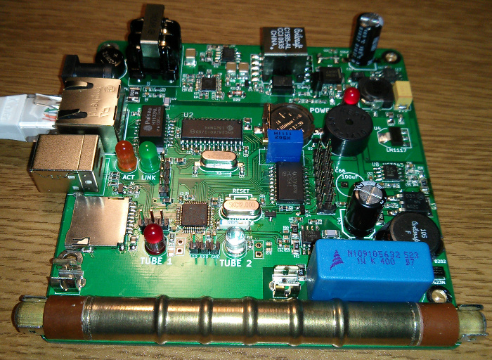
Features:
	STM32F103C8 MCU (LQFP-48; 64K flash, 20K RAM)
	ENC28J60 based 10Mbit ethernet
	LM5070 isolated flyback supply (48V in, 12V output)
	Additional switching supplies for +5V and HT
	HT rail is adjustable for different tubes
	Supports dual tubes for high and low range, or tube comparison.
	High side detection so that tubes may be grounded.
	Micro SD card slot for logging data.
	LEDs and piezo sounder to indicate radiation events (controlled by MCU).
	HD44780 LCD interface
	I2C connector for Slavtek HT16K33 I2C LED eight digit 14-segment display.
Shown with Soviet tube SBM-20. Open slot designed for SI-3BG for apocalypse-level radiation monitoring. Software is still under development.
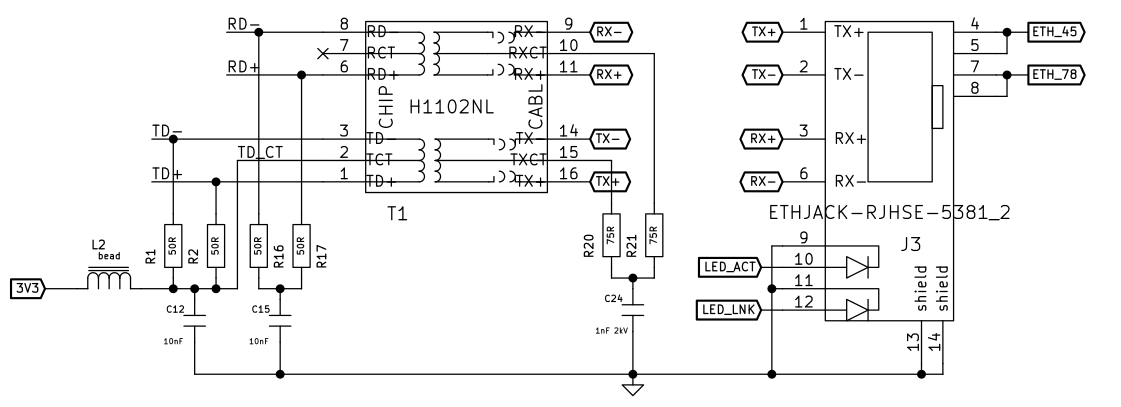 Ethernet jack & magnetics:
The spare pairs (4/5, 7/8) supply 48V DC to the device.
Ethernet jack & magnetics:
The spare pairs (4/5, 7/8) supply 48V DC to the device. 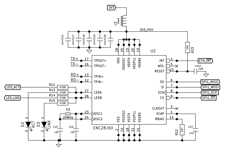
ENC28J60 MAC & PHY: ENC28J60 is an SPI controlled MAC & PHY IC. Depedning on silicon revision, Rbias should be 2.32k or 2.7k. More recent ones all use 2.32k, I think.
48V to 12V flyback supply and 802.3af PD signalling:
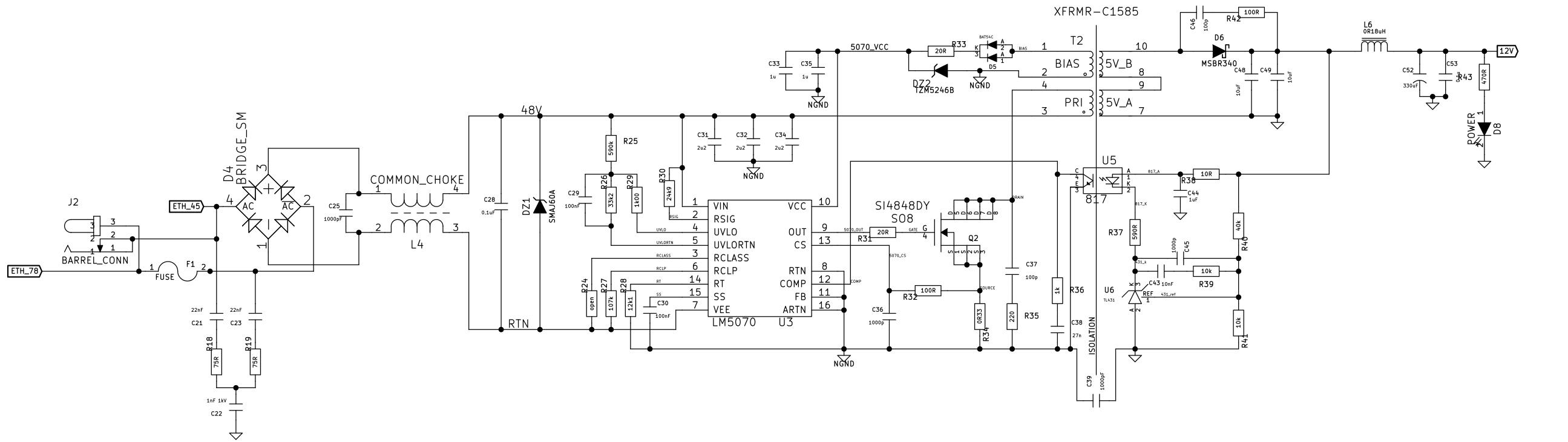
Fairly standard current mode flyback supply (isolated), the only exception being that the LM5070 has some extra signalling to communicate with the PoE injector/switch, and doesn't fill it's capacitors or run until things have been negotiated. Once negotiation is complete,it connects the 48V input "gnd" (RTN) to the primary ground (NGND) - which is isolated from the ground of the rest of the device (GND). With L6 = 4.7uH the feedback oscillates quite badly. In the end just shorting L6 entirely provides good performance.
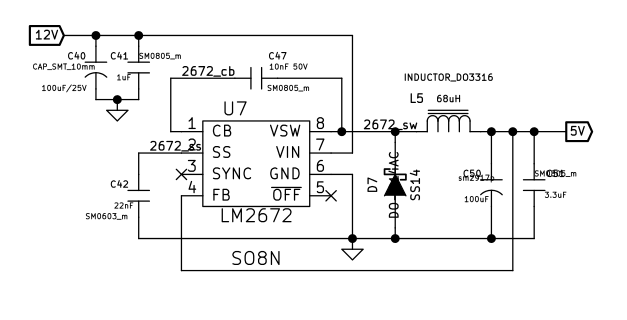
12V to 5V buck converter.
Pretty straightforward.
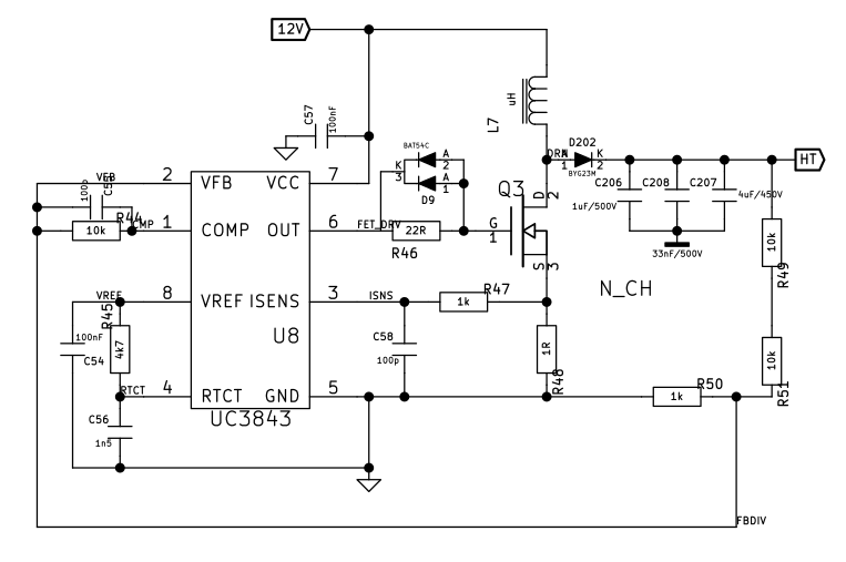
Adjust R49 & R51 to adjust output voltage. 170 - 180k combined is good for ~400V. Rt/Ct (R45, C56) should be 10k & 10nF. That should put it in the 20kHz neighbourhood.
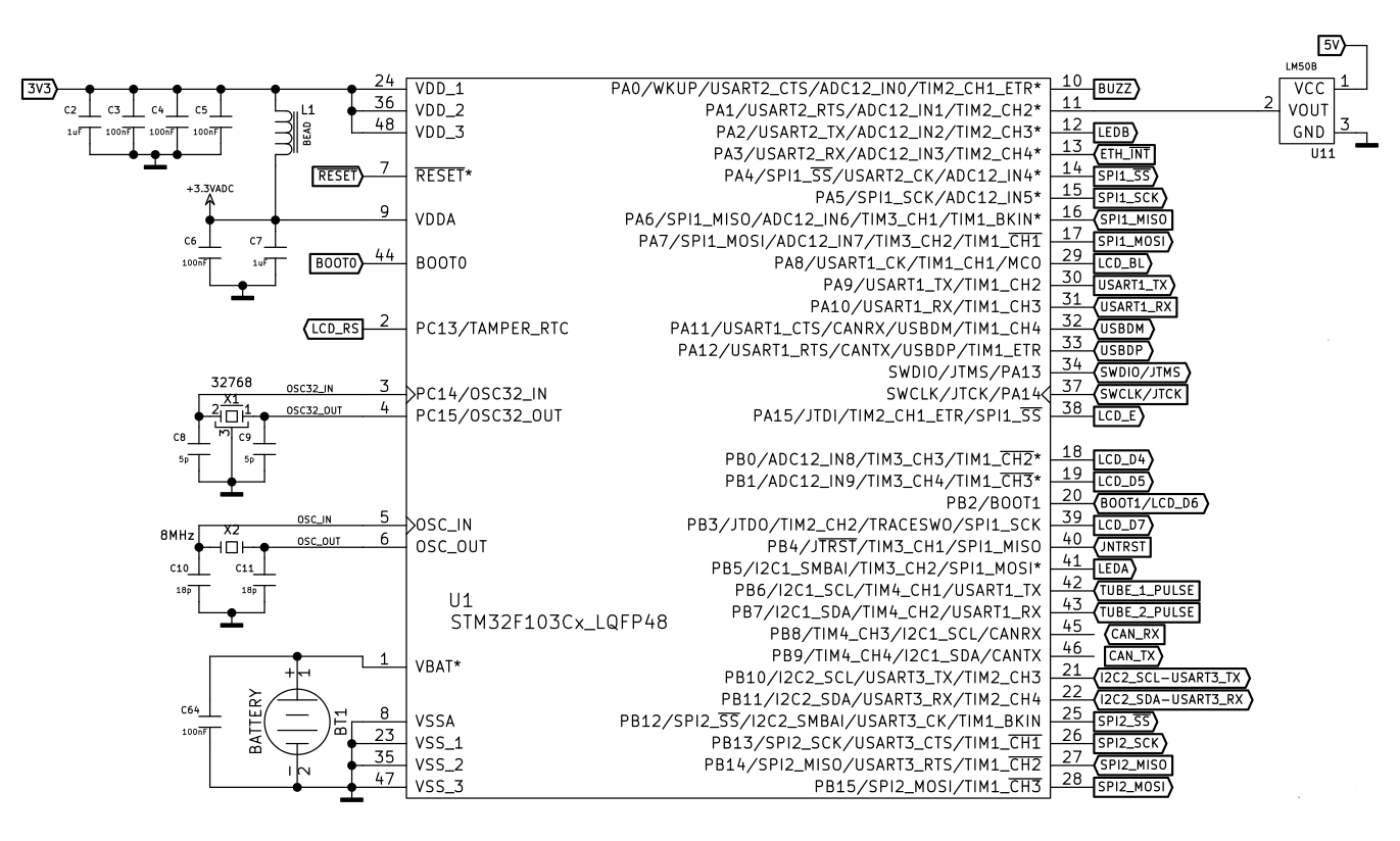
The main crystal can be any multiple of 72MHz in the 4...16MHz range. LM50 is an analog temperature sensor.
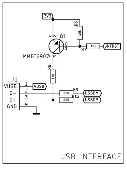
A low signal at PB4 (JNTRST) pulls the USB D+ line high, causing the host to see our device.
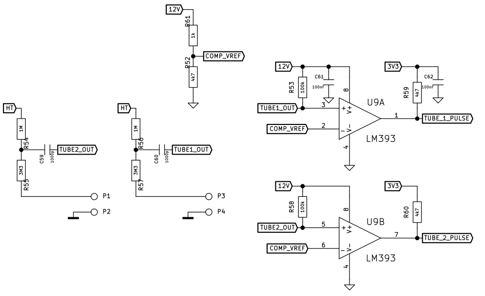
Geiger tube interface and pulse level shifter: Pulses from the geiger tube are capacitively coupled onto the + input of the comparator. When the pulse goes below +10V (COMP_VREF), the output of the comparator pulls low and fires an interrupt on the STM32. With 1000pF and +10V Vref, the pulse lasts about 25us. Maybe it should be reduced a bit (to say, 100pF) for better performance with closely spaced events.
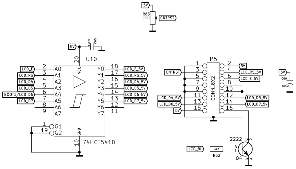
LCD interface (Level shifted for 5V HD44780 LCD): PWM output to control backlight brightness.
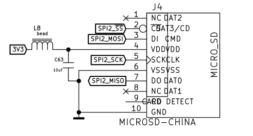
SD card connector: Wired in SPI mode.
Documentation on this item is currently incomplete. Email for now if you have any questions.